October 21 2026
 3 min read
Variable demand, pump efficiency and system reliability
Managing changing flow demand without wasting energy or shortening pump life is a challenge in many industrial processes. A pump selected for peak duty may spend much of its working life operating at significantly lower flow. That does not automatically make a variable frequency drive (VFD) the right solution: the best approach depends on the pump curve, system curve and liquid being handled.
The starting point is to understand the full operating range, including minimum, nominal and peak flow, static head, pipework friction and any solids-handling requirements. Flow can be controlled by changing pump speed or impeller diameter, changing system resistance or using more than one pump. Each approach has trade-offs.
Why throttling and bypass control can be costly
A fixed-speed centrifugal pump is sometimes controlled with a discharge throttling valve. Closing the valve increases system resistance, reducing flow and moving the operating point along the pump curve. This is a legitimate control method, but depending on the selection and duty, excessive throttling can increase energy consumption and push the pump outside its preferred operating region.
A bypass or recirculation line sends part of the pumped liquid back to a tank or an appropriate return point. It can help maintain a required minimum pump flow, but the energy used to circulate that liquid may be substantial. The bypass must be engineered for the duty, rather than assumed to be a cure for every low-flow condition.
Where a VFD makes sense
A VFD changes motor speed and therefore the centrifugal pump curve. For a given impeller diameter, the pump affinity laws provide a useful starting point:
- Flow (Q) is approximately proportional to speed (N).
- Head (H) is approximately proportional to speed squared (N²).
- Power (P) is approximately proportional to speed cubed (N³).
For example, reducing speed to 80% of its original value gives a theoretical power ratio of 0.8³ = 0.512: around a 49% reduction under comparable, idealised conditions. This is not a promise of a 49% saving on site. Actual input power and energy savings depend on the operating point, static head, pump and motor efficiency, and the control regime.
VFDs are especially attractive in friction-dominated systems, where reducing flow also reduces the head required to overcome friction losses. In systems with a large static-head component, the pump still needs to overcome that fixed head at reduced speed, limiting available turndown.
Why reducing speed has limits
Reducing speed does not simply move the same duty point to a lower flow. The intersection of the reduced-speed pump curve and the system curve determines what the pump can actually deliver. At sufficiently low speed in a high-static-head system, the pump may be unable to overcome the required head, resulting in little or no delivered flow.
The permissible operating range also depends on hydraulic stability, minimum flow requirements and the nature of the liquid:
- Solids transport: Slurry and effluent lines must maintain suitable carrying velocity to limit settling and blockage. A pump may be turning safely while the downstream line is not transporting solids adequately.
- Low-flow operation: Running below the manufacturer’s minimum continuous stable flow can result in recirculation, vibration and hydraulic damage. Minimum thermal flow is a separate consideration, particularly at low or no flow.
- Operation away from BEP: Prolonged service outside the recommended operating region can increase loads, vibration and wear. The allowable region should be checked against the manufacturer’s guidance.
- High-flow operation: Excessive runout can increase NPSH required and may create risks such as cavitation, motor overload on some pump designs and faster abrasive wear. This is different from deadheading, which means operating with essentially no discharge flow.
Temperature, volatile liquids, abrasive solids and changes in fluid properties can further affect suction performance, materials selection and control settings. The minimum and maximum acceptable flow should therefore be determined for the actual duty, not estimated from motor speed alone.
Alternatives when one pump cannot cover the duty
When demand varies widely, the best solution may be a different pumping arrangement rather than a single large pump with a larger turndown requirement.
These are design options, not interchangeable fixes. Selection should account for capital cost, controls, redundancy, maintenance access and the consequences of failure, as well as energy consumption.
| Configuration | Suitable situation | Important consideration |
|---|---|---|
| Parallel pumps | A wide range of flow demand | Start and stop pumps to match demand; check combined curves, minimum flow and control sequencing. |
| Series pumps (staged head) | High total head requirements | Pumps add head; verify maximum inlet, discharge and casing pressures, seals and transient conditions. |
| Buffer or break tank | Short-term peaks or variable upstream/downstream demand | Separates demand patterns where process and space permit; check storage volume, controls and solids settling. |
| Centrifugal and positive displacement combination | Bulk transfer plus a genuinely separate, accurately metered flow requirement | Can be appropriate for compatible fluids and hydraulic arrangements; confirm pressures, control logic and equipment suitability. |
An application example: quarry dewatering
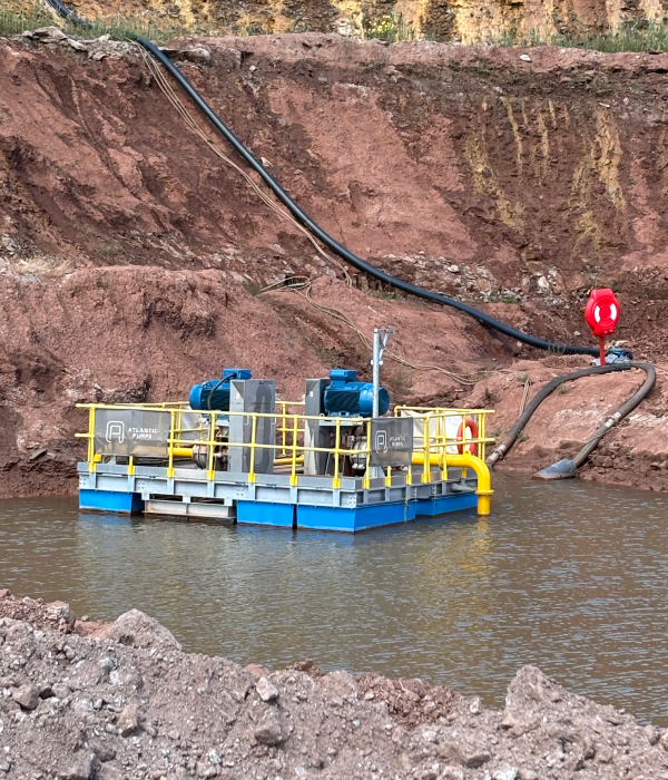
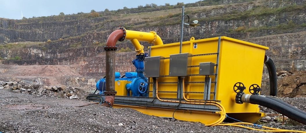
Quarry dewatering illustrates why flow and head should be considered together. Water levels, discharge elevations and site layouts can change during an operation. In deep applications, a staged or intermediate-tank approach may help manage the required total lift. However, the best arrangement depends on the site hydraulics, pressure ratings and operational requirements.
Figure 1. Example of quarry dewatering pumping equipment.
A practical checklist before changing the control method
- Plot the pump curve against the system curve at minimum, nominal and peak duty.
- Confirm static head, friction losses, fluid properties, solids content and line velocity.
- Check minimum continuous stable flow, minimum thermal flow, NPSH margin and the recommended operating region.
- Compare throttling, VFD control, pump staging and storage using whole-system energy and lifecycle costs.
- Check that the proposed control philosophy protects the pump during startup, low demand, peak demand and fault conditions.
The right control method starts with the system
A VFD can provide useful energy savings and improved control, but only when the pump and system characteristics support it. Where static head, solids handling or a very wide duty range impose limits, staged pumps, a carefully designed buffer arrangement or a revised pump selection may be more robust.
If your process demand changes throughout the day, speak to Atlantic Pumps about reviewing the duty points, pump curves and operating constraints before specifying a new control arrangement.
Further Reading
Blog: Sizing Centrifugal Pumps for Variable Demand
We also take a sustainable approach to our work and are committed to reducing energy waste from pumps. Our expert knowledge allows us to reduce energy usage by 20% on the average site!
Call us today on 0800 118 2500 for more information.