August 28 2025
 7 min read
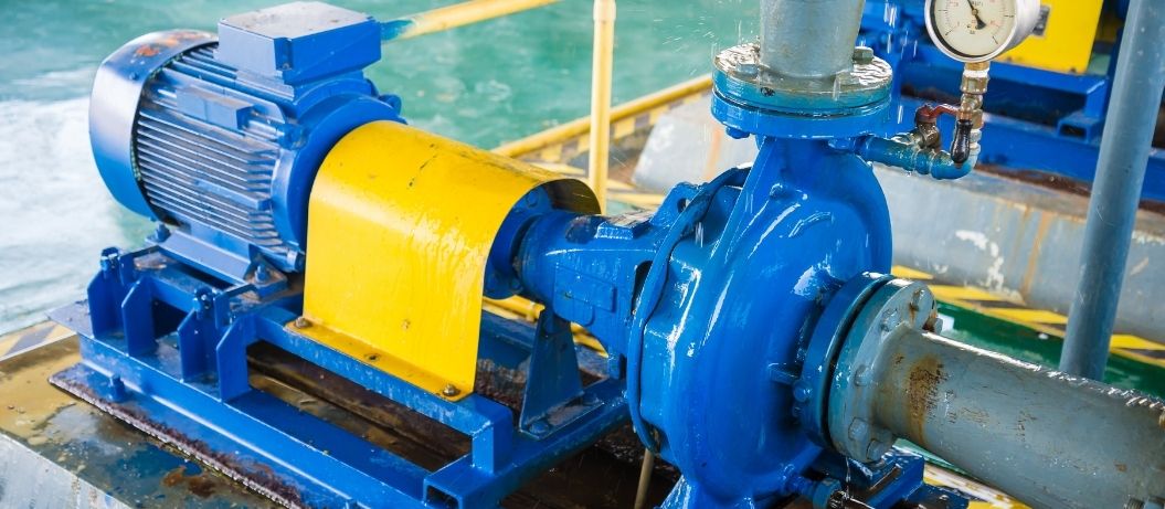
There could be several reasons why a pump is failing to achieve the desired flow, including improper pump selection, inadequate system design, and insufficient maintenance.
The pump manufacturer will be able to provide a ‘curve chart’ showing your centrifugal pump’s rated flow and head performance, but what if the pump isn’t delivering the performance expected of it?
In this article, we guide you through some practical methods for assessing pump flow performance, utilising your general observations and site experience.
Before we get too far in, let’s just clarify what we mean by “Flow” – are we talking volume or speed?
Flow-rate
Centrifugal dewatering pumps are often used in applications where a minimum flowrate performance is essential. It might need a certain flow rate (its volume in a given time) to match the system requirements, such as feeding process water into a hydro-cyclone, or dewatering a location to prevent flooding.
Flow-rate is expressed as volume/time, eg 15L/min or 30m3/hr
Flow Velocity
Alternatively, you might be more concerned with flow velocity – the actual speed of the fluid – rather than its flow rate. This typically occurs when a minimum flow velocity is required to prevent suspended solids from settling out or to prevent air pockets from forming in bends and cavities. In many cases, we can increase the flow velocity by decreasing the pipeline diameter, provided the pump can handle the additional friction and still achieve the required head.
Flow velocity is expressed as distance/time, eg 2m/sec
Diagnosing Flow Issues
We assume that if you’re reading this, the pump has already been chosen, so we won’t rub it in about the importance of proper pump selection at this stage! However, if you can see that the pump’s rated performance will simply never achieve the required performance, then grab our guide “Industrial Dirty Water Pump Selection”
You might have a hunch from your on-site experience and any knowledge you have of the pump’s history, so be free to hop right to the issue you think is most likely:
- Incorrect Installation
- Wear and maintenance (of pump and system)
- System changes (pipework, valve additions, new equipment connected etc)
- Fluid parameter changes (viscosity, temperature, solids content)
- Pump upgrade: when selecting a better-matched pump might be your best choice.
Installation: The flow hasn’t been good from the start
Let’s go back to the beginning.
Always follow all the installation, commissioning, and user instructions provided by the pump manufacturer. Speak to the pump provider if you have any concerns or missing information.
Having given that disclaimer, here are some general tips to consider when installing a centrifugal pump:
Pump location
Centrifugals have low suction lift capacity. If possible, install the pump below the water supply so that it ‘floods’ into the chamber under gravity – effectively making it ‘self-prime’. This avoids priming and many intake cavitation issuesThree most common options for centrifugal pump siting:
- Flooded suction (Dry-sited pump types)
This arrangement is the most advantageous for centrifugal pumps, as it gives you the best possible net positive suction head (NPSHa) and is self-priming.
However, it is often not possible to site the pump intake below the supply.
- Suction-lift (Dry-sited pump types)
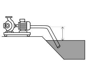
If the pump does have to be above the water level, for example when abstracting from a stream or dewatering a lagoon, keep the intake pipe short as short and direct as possible, ensuring it remains within the pump’s suction-lift capabilities. Every pump design has a minimum Net Positive Suction Head requirement, abbreviated to NPSHr, which can be obtained from the manufacturer.
If site conditions or the risk of rising water levels don’t facilitate this ‘dry-sited’ placement, consider using a high-head submersible pump (see below).
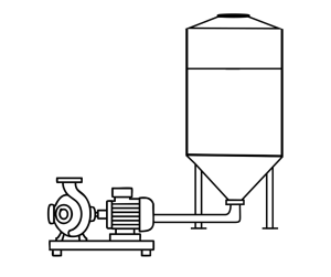
Another concept is to install a buffer tank that’s fed by a small submersible pump to act as a priming system. This tank feeds the main, high-head pump at a positive intake pressure. Examples of this in operation include a deep quarry dewatering system in Wales, and a mine dewatering rig in eastern Europe.
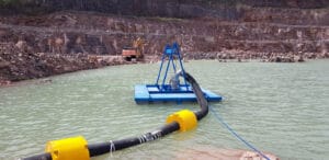
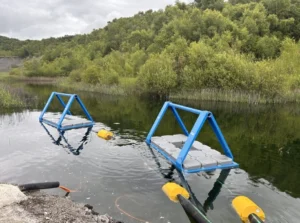
- Submerged (Fully-sealed, submersible pump types)
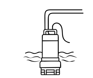
Submerged pumps are available that are suspended within the water body and can be controlled via level sensors. There are a number of case studies showing how these pumps can be suspended on a pontoon, for easier inspection and maintenance.
Wiring of 3-phase pumps
For 3-phase pumps, check that the impeller is rotating in the correct direction, as incorrect wiring can cause the pump to run in reverse. Centrifugal dewatering pumps still function to some extent when operated in reverse, but they deliver significantly less head pressure and flow rate. Either check the motor’s rotational direction before coupling it to the pump, or perform a quick start and stop – we call it a “bump” – which should be enough to sense which way the impeller is spinning. Check this against the pump documentation/installation instructions, as it is all too easy to wire the two live phases up incorrectly on 3-phase pumps.
Check the straight lengths on the pump inlet and outlet
Ensure that there is a straight section of pipework on either side of the pump, which is unimpeded by valves, bends or blockages. This reduces the chance of intake cavitation and turbulence that can cause a low flow, along with accelerated pump wear.
Also, ensure that the suction pipe is positioned horizontally or on a continuous rise from the inlet strainer to the pump. Any ‘n’ or ‘u’ shapes in the pipework (especially on the suction side) will likely lead to airlocks, which can reduce or even stop the pump flow.
Check that the suction supply isn’t whirlpooling, as this can cause the pump to pull in air, leading to reduced flow rate and often cavitation. Allowing the water level to rise before the pump is turned on might provide enough net positive suction head (NPSH).
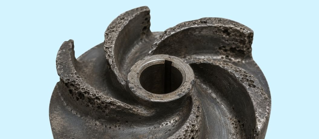
Wear and maintenance issues
If the flow has deteriorated over time and the system hasn’t changed, your reduced flow rate is likely due to internal wear of the pump’s wet parts, or debris building up and restricting the flow. Pressure gauges before and after a pump are very useful for identifying if the trouble is within the pump or the pipework. In the absence of these, the pump and pipework sections will need to be opened up for inspection.
Depending on duty, you may see signs of wear or damage as pitting, chipping, or a shiny, polished off look. As the gap between the impeller and volute increases, performance decreases. Flow decreases proportionally to wear, and energy consumption increases – quite dramatically on some types of pumps.
It’s not just pumps that wear – pipework can break down, collapse, or delaminate internally, causing blockages and a restriction of flow (friction).
See the article “Pro-active Maintenance of Dewatering Pumps” for further guidance on setting up a pump maintenance program.
System growth
It’s very easy to increase the demands on a pump over time, without factoring in the overall effect on the head pressure needed; adding new components or connected equipment, changing the pipeline route, or increasing the head height can take the system requirements beyond the pump’s BEP (best efficiency point).
Routing pipework around obstacles, rather than looping over them, can help avoid dips and high points where airlocks can occur. Where the system cannot avoid “n” shaped bends, air vent valves should be fitted on them.
Do you have an up-to-date inventory of your pumping system? ’Walking the line’ and recording the pipe diameters, head height (elevation difference), plus lengths between bends and components, enables a calculation of the total dynamic head (TDH) pressure required. Is it within the design parameters of your pump?
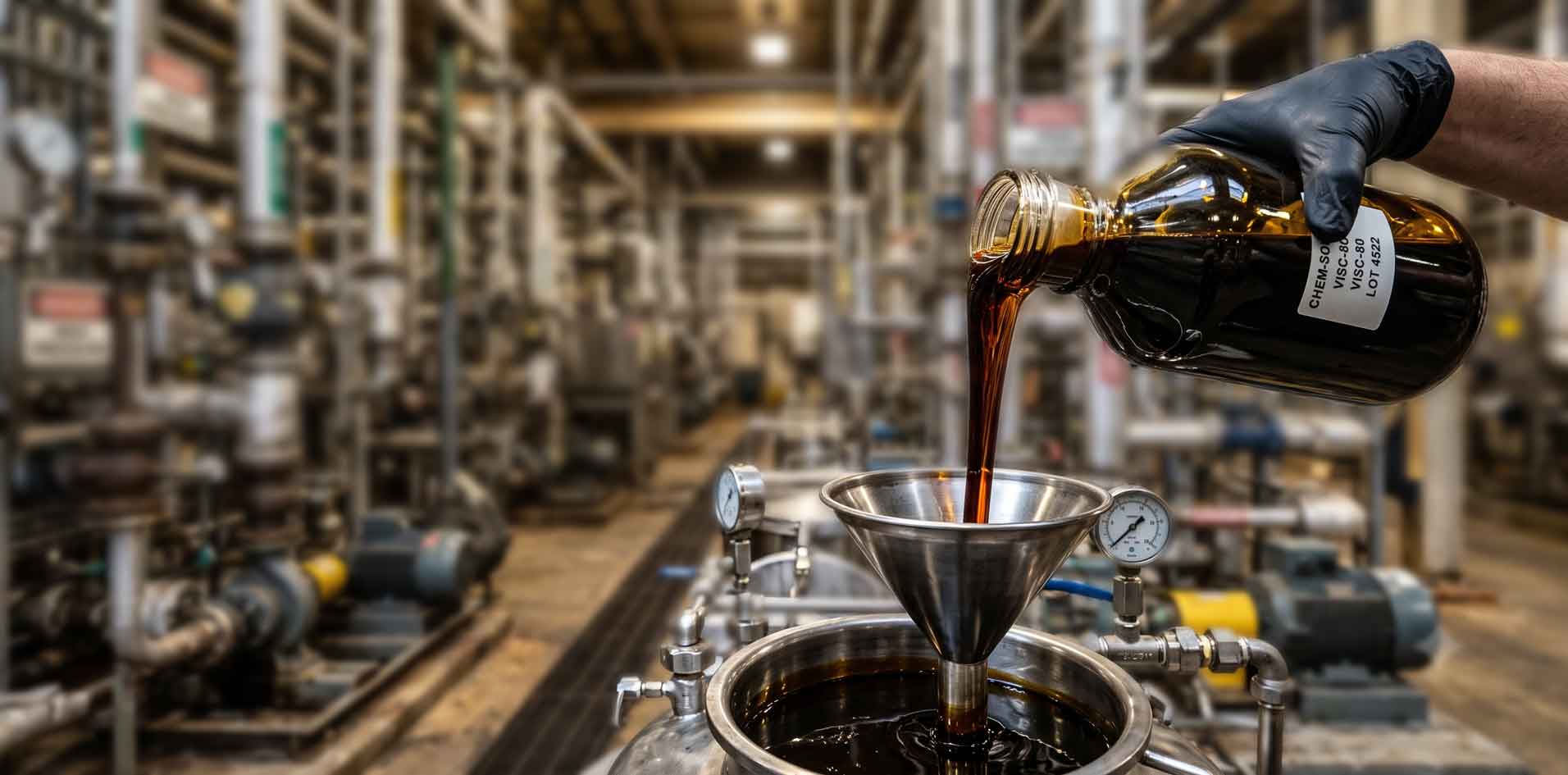
The Fluidity of Fluid Properties
The viscosity of a fluid can be defined as its’ level of resistance to flow, which can be affected by the likes of:
Solids content – suspended (entrained) or dissolved. Most pumps’ flow and head ratings are based on the specific gravity of clear water (1.0 s.g)
Temperature – extremes can lead to freezing or vapourising. Between these extremes, most fluids experience higher viscosity as temperature drops.
Thixotropic and rheopectic fluids – These terms might sound fancy, but they are more common than you might think. With these fluids, the viscosity of these fluids changes inline with shear stress. A rheopectic (anti-thixotropic) fluid might flow freely in the tank, but it stiffens up when subjected to high-shear forces. This can happen suddenly from centrifugal force within the pump, or over a long line of pipe as it runs against the inner surface. Conversely, a thixotropic fluid might flow well once it’s moving, but gel up and seize the impeller when the pump is turned off.
Pump Upgrades
With your system well maintained and optimised, and the pump in good repair, what do you do if you’re still not getting enough flow?
Three pump upgrade options to consider:
- Re-configure your existing pump. The overall performance of a Centrifugal pump is determined by its components, some of which are often interchangeable:
- Electric motor
- Pulley transmission or direct coupling
- Impeller
By changing just one of these essential pump components, you may be able to meet your system requirements without needing to replace the entire unit.
- Install a second pump (booster)
- A secondary forwarding pump can be connected in series to extend the head height. A buffer tank is recommended to feed the forwarding pump, protecting it from surges and suction pressure dips.
- A parallel pump can increase the flow rate, but back-check valves may need to be fitted.
- Choose a better-matched pump. We know, from experience, that the right pump for the duty results in less energy consumption, reduced maintenance, and increased longevity and consistency in performance. A pump upgrade doesn’t always cost more; the right pump for the duty will likely save a significant amount of money during its lifetime.
Industrial Dirty Water Pump Selection
A pump buyer's guide to dirty water management.
Conclusion
Getting to the root of the issue can be frustrating and time-consuming – but Atlantic Pumps are here to help. We can diagnose and fix industrial pump issues onsite or at our workshop – simply connect with our mobile pump engineers via phone at 07537 149 180 or WhatsApp
We also take a sustainable approach to our work and are committed to reducing energy waste from pumps. Our expert knowledge allows us to reduce energy usage by 20% on the average site!
Call us today on 0808 196 5108 for more information.