February 11 2026
 6 min read
This is an in-depth series from the Atlantic Pumps Academy. You can also watch on-demand training presentations and sign up for live webinars to expand your pump knowledge.
At-a-glance
- Pressure is created by the system, not the pump — a PCP simply builds enough internal force to overcome system resistance.
- As a positive‑displacement pump, a PCP will continue increasing pressure until the system yields or a mechanical limit is reached.
- Flow remains nearly constant regardless of pressure, making PCPs ideal for viscous, high‑SG, or pressure‑variable duties.
- Safe systems require over‑pressure protection, typically via pressure switches or controlled relief systems.
- Maximum pressure capability depends on stage count, rotor–stator geometry, torque, fluid properties, and pump condition.
- Manufacturers often derate pressure limits to improve pump life and reliability—especially for abrasive or other challenging fluids.
- Higher required pressures can be achieved by upgrading components, selecting a multi‑stage/short‑pitch design, or installing pumps in series.
Why pressure matters in PCPs
Progressive cavity pump pressure is one of the most frequently quoted – and commonly misunderstood – parameters in pump specification and selection.
It is the system’s resistance to flow, not the pump that mandates the pressure. A pump that can handle this back-pressure has to be selected.
If the pressure generated exceeds the weakest point of the system, failure will occur at that weak point. This might result in leakage, sudden explosion, mechanical failure, motor burnout, or the power supply tripping out.
How Progressive Cavity Pumps Generate Pressure Internally
As stated earlier, the pressure itself arises between the system’s resistance and the pump’s counter-force.
In other words, the pump must be strong enough to handle the back pressure, or resistance, from the system. The maximum pressure a PC pump can handle depends on torque, mechanical strength, and seal integrity.
Because the PC pump is a positive-displacement (PD) pump, it will attempt to deliver the same volume of fluid regardless of the resistance. To do this, it “builds” internal pressure within its sealed cavities until it exceeds the system’s backpressure. If the system’s resistance is 5 bar, the (suitably rated) pump will discharge at just over this pressure to force the fluid out.
Pressure is not generated at a single point within the pump. Instead, it is distributed incrementally within each cavity along the length of the rotor–stator assembly. Each cavity pitch (or stage) contributes a small pressure increase, and the total differential pressure is the sum of all stages. One stage is defined as the stator’s complete pitch length (the length of two rotor pitches), with ‘single stage’ and longer ‘multi-stage’ models available. PC pumps are often rated at 6 bar per stage, but this isn’t a given standard.
Short-pitch geometry PC pumps have a larger sealing line-to-cavity volume, which increases the pressure gain per stage. It also allows more stages to fit within the same pump length, and as we know, adding stages increases the maximum pressure rating.
How do PC pump pressures compare to centrifugal pumps?
Factor |
Centrifugal Pumps |
Progressive Cavity Pumps |
| Pressure ‘creation’ | Kinetic energy (velocity) generates pressure (potential energy) within the volute by centrifugal force. | Torque resists backpressure as the fluid is forced along through a positive displacement action. |
| Flow & pressure | Inversely proportional. Flow curves off dramatically as system pressure/head increases. | Independent. Flow remains near constant regardless of pressure. |
| Rotational speed affect on flow and pressure | Flow is linear, pressure is squared. | Flow is directly proportional to rotation speed. Pressure builds to meet system resistance. |
| Effect of system pressure exceeding pump’s capabilities | Zero flow as the pump ‘dead heads’. Fluid recirculates, dissipating energy through heat. | Backflow (slipping/internal leakage), leakage from seals, and dangerous pressure buildup (without a relief mechanism). System failure, tripping out, or motor burnout. |
| Suction pressure | Have low-to-no suction pressure, require priming or ‘flooded suction’ supply. | Strong self-priming/suction lift capabilities. |
| Viscosity and specific gravity | Thicker fluids can reduce head and flow, requiring pumps to be upsized to compensate. | Thicker fluids can improve efficiency. Head pressure and flow are unaffected (torque dependent). |
Unlike centrifugal pumps, PC pump (PCP) pressure is independent of flow-rate – it is a reaction between mechanical torque and system resistance. The pump generates whatever pressure is required to move the fluid, up to its mechanical and hydraulic limits.
This characteristic is both a strength and a risk. It makes PCPs ideal for accurate dosing and flow control in pressure-variable systems, even with high-viscosity fluids. On the flip side, it also means the pump can unknowingly operate at high internal stress if system pressure is underestimated, changes over time or spikes for some reason. Because of this, pressure should always be defined from a full system perspective, incorporating static head, frictional losses, downstream process conditions, and the risk of system upsets, such as a blockage on the discharge side.
Unlike a centrifugal pump, which adds to the supply-side pressure, a PC pump experiences only the differential pressure. So a PCP with a net positive suction head of 2-bar and a discharge head of 6-bars only experiences 4 bars of internal pressure. Another key difference to understand is that discharge pressure from a PCP pump is unaffected by changes to flow rate/rotational speed.
Centrifugal pumps have an inverse relationship between flow and pressure, where higher discharge pressure reduces flow, and vice versa. A PCP will deliver a near-constant flow regardless of system pressure; until it reaches its maximum differential pressure or until slip (internal leakage) becomes significant.

Centrifugal pump head-pressure is affected by specific gravity (SG), with ‘heavy’ fluids having less head than water, even if the pump discharge pressure is the same. PCPs handle high specific gravity (SG) fluids by drawing more power, making them ideal for high SG sludges and pastes.
Multi-stage centrifugal pumps can generate up to around 16 bar and maintain good flow rates, but are best suited to low-viscosity liquids. By comparison, multi-stage PC pumps are available in models up to 48 bar; even greater in some highly specialised fields.
PC Pumps compared with Piston (ram) pumps
Piston pumps often exceed PC pumps on overall pressure ratings, and are suitable for low-viscosity, non-abrasive, Newtonian (non-shear-sensitive) fluids. In contrast, PC Pumps handle a wider range of viscosities and generate a steady, low-shear flow and non-pulsating pressure.
PC Pump Over-Pressure Protection
Because a progressive cavity pump is a positive displacement pump, it will continue to build pressure until either the system yields or the pump reaches a mechanical limit. Unlike centrifugal pumps, there is no inherent flow reduction as discharge pressure increases. As a result, over-pressure protection is not optional in PCP systems — it is a critical safety and reliability requirement.
There are two common methods to achieve over-pressure protection; electrical circuit cut-off via a pressure switch, and pressure release valves (PRV).
Pressure Switches
Designing the motor’s power supply to trip out before dangerous pressure is reached is a good protection measure.
- Mechanical switches directly open or close a set of electrical contacts at a predefined pressure.
- Electronic pressure transmitters convert pressure into a continuous signal, allowing shutdown logic to be implemented in a PLC or VSD
A basic switch can cut the power when maximum safe pressure level is reached, allowing for invention and manual reset once the problem, such as a blockage, is cleared.
Pressure Release Valves (PRVs)
On pumping systems, PRVs are used to divert flow when pressure reaches a set maximum, with the aim of reducing system pressure as a result. Passing the fluid back to the pump intake (discharge-to-suction bypass) is a common method. However, the mechanical stress on the pump remains, and the shaft seals in particular are subjected to the full pressure.
In summary, here is why over-pressure return loops are not usually the best approach:
- Energy is wasted.
- It hides the problem until the reduced flow becomes noticeable in the system’s downstream performance.
- While it might protect the downstream system from pressure spikes, it doesn’t protect the pump, as in-pump pressure remains unaffected.
- It can reduce NPSH margins, where return flows are high.
- Excessive recirculation increases intake temperature and wear rate.
- It makes it difficult to diagnose low-flow issues as return flow can simulate a worn rotar/stator assembly.
PRVs have their place, but misconceptions abound. As an alternative to returning flow back through the pump, diverted flow can be sent onwards, via a bypass line. This duty/standby type pipe arrangement is good for blockages, but isn’t often feasible on longer pipe runs.
Progressive Cavity Pump maximum pressure rating
PC pump marketing material tends to present pressure capability as a simple headline figure, often a 6-bar rating per stage. Each ‘stage’ is defined as one full pitch or ‘twist’ of the stator that creates the cavity. A multi-stage PC pump is simply a longer one that has multiple pitches along it stator’s length.
While the 6bar (87psi) pressure per stage rating is common quoted for PCPs, in reality, there is no inherent design reason for this particular maximum pressure; generally the longer the rotor and stator assembly is, the higher the maximum pressure capability. If the sealing line of each cavity withstands 6-bar of differential pressure, a two-stage can handle 12-bar.
Pressure interacts with factors that are commonly thought of in isolation: solids content, abrasiveness, temperature, suction conditions, and running speed. A PCP that performs reliably at a given pressure on clean water may suffer rapid degradation on thickened sludge at the same differential pressure. Understanding pressure in isolation is therefore insufficient; it must be considered in the context of the complete duty.
The case for de-rating PC pump pressure
PC pump manufacturers usually derate the pump’s allowable pressure by subtracting a margin from the tested/assessed maximum. This is for increased performance, longevity, and safety.
Running a PC Pump at or near it’s maximum pressure shortens its lifetime and increases maintenance, especially so with abrasive fluids or high flow-rates.
Abnormal pressure spikes can easily break a pump, and increase the risk of explosion injury or harm from chemical leakage.
System engineers might decide it’s worth derating pumps further than the manufacturer has, to reflect challenging operating conditions such as abrasive or hot fluids. They will therefore opt for a higher-rated pump than technically required, paying more upfront (capital) in exchange for operational savings (OPEX).
How do you increase the maximum pressure rating?
A higher pressure might be needed, for example, to increase head, or to feed a pressure-dependent process. Options depend on the situation, but can include:
- Replacing the pump with a larger one
- Upgrading the ‘weak’ points of an existing pump
- Direct connection of an additional pump.
Replacement: The simplest method is to simply replace the pump with one better matched to the duty, such as swapping a single stage 6 bar with a multistage 9 bar. Alternatively, going from a high-flow long pitch to a higher-pressure short-pitch model could be an option.
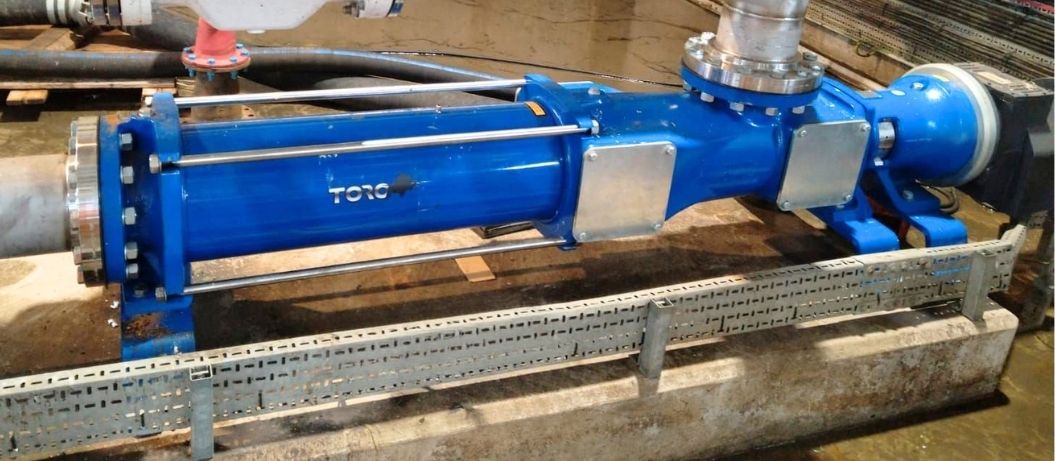
If an older pump is facing the cost of an overhaul, it is certainly worthwhile getting a price for a newer version. Modern PC pumps like the Toro-Kronoa range are an upgrade in performance and running cost on many legacy PCPs, and can even cost less than rebuilding a worn-out asset.
Upgrade: If the rest of the pump is robust, a larger motor or seal upgrade could potentially achieve higher pressure capability.
Single-stage to Multi-stage: Adding an identical PC pump in series is technically possible; it essentially adds more stages. As they’re run on different motors, it does require careful speed co-ordination to match the flow rate. The advantage lies in the pressure gain and stress being shared among the two pumps’ motors, drive shafts, and stators, improving lifetime and reliability.
Conclusion
Hopefully, you now have a better understanding of pressure in the context of progressive cavity pumps. If you need to improve the efficiency, longevity, or safety of your on-site pumping operations, please contact us by phone, online, or email.
Don’t forget to check out other training formats and to sign up to our Pump Academy newsletter
Download “What’s wrong with this pump? Pump Health Diagnosis”
We also take a sustainable approach to our work and are committed to reducing energy waste from pumps. Our expert knowledge allows us to reduce energy usage by 20% on the average site!
Call us today on 0808 196 5108 for more information.